

How High-Frequency Soldering Actually Works
There are two ways to get heat into a soldering tip.
The familiar one is a resistive element — a coil of wire or a ceramic heater — pressed against or inserted into the tip. Current flows, the element gets hot, and heat conducts across the interface into the tip and out to the working face. It works, and it has been the standard for decades. Its limitation is structural: the heat is made somewhere other than where it is used, and it has to cross a boundary to get there. Every boundary is a thermal resistance.
The second way removes the boundary. Instead of heating the tip from outside, you make the tip itself the heater.
Eddy currents, briefly
Put a conductor in a changing magnetic field and currents are induced inside it. Those currents meet the conductor’s own resistance and dissipate as heat. No contact, no separate element, no interface — the metal doing the work is the metal getting hot.
The catch is that the current does not spread itself evenly. At higher frequencies it crowds toward the surface of the conductor, a phenomenon called the skin effect. How deep it penetrates depends on frequency, resistivity and permeability. Drive a soldering tip at a couple of hundred kilohertz and most of the induced current is flowing in the outer layer of the tip body.
That is the whole trick. Drive the tip with a high-frequency alternating magnetic field, and the tip’s own surface layer becomes the heating element.
What it looks like on a scope
This is measurable, so let us measure it rather than describe it. The three captures below were taken at three points in our own stations.
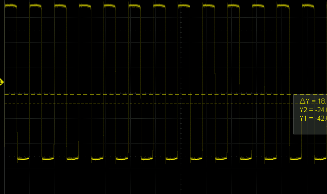
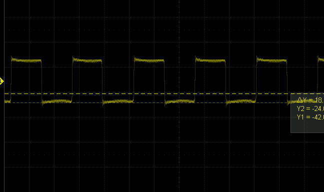
| Measurement point | Waveform | Frequency | Peak-to-peak |
|---|---|---|---|
| Transformer primary | Square | 4.91 µs period | 320 V |
| Transformer secondary | Square, rounded edges | 4.90 µs period | 100 V |
| Output, at the load | Sine | 203.00 kHz | 210 V |
One thing in that table is worth flagging rather than glossing over: the amplitude rises from 100 V at the secondary to 210 V at the load. A network that merely passed the signal along would lose voltage, not gain it. What sits between the transformer and the tip is doing more than conducting — but that is a circuit-design discussion, and this article is about what reaches the tip.
Why the shape matters
A square wave is not a single frequency. It is a fundamental sine plus every odd harmonic of it — third, fifth, seventh, and onward, each weaker than the last but all of them present.
Feeding those harmonics into a work coil does not heat the tip any better. They do three other things instead:
- They radiate. A harmonic at 600 kHz, another at 1 MHz — those are radio frequencies, and a work coil is an antenna. That is interference looking for somewhere to go: an unshielded sensor on the same bench, a nearby instrument, a radio.
- They stress insulation. Peak voltages add. A drive designed around a clean sine can be built with less insulation margin than one that has to survive harmonic peaks.
- They waste energy. Power delivered into harmonics that do not couple usefully into the tip is power that never reaches the joint.
Filtering the drive down to a clean sine by the time it reaches the load is not cosmetic. It is the difference between a station that behaves predictably on a bench full of instruments and one that does not.
What this architecture actually buys
Because the heat is generated in the tip body rather than conducted into it, there is no heater-to-tip interface to cross. The thermal path runs from the outer layer of the tip — where the heat is made — inward to the working face, through one piece of metal.
In practice that is what shows up as fast recovery on heavy joints. A resistive heater has to push heat across its own boundary under exactly the conditions where the tip is losing heat fastest, and that boundary is where the delay lives. Remove it and the control loop has less thermal inertia to fight.
What it does not buy
Worth being plain about: this is a different thermal architecture, not a free lunch.
The heat still has to reach the joint, and the joint still has to be able to absorb it. A high-frequency station on a huge copper plane will still lose temperature, because the bottleneck moves to the tip-to-work interface. Wattage still matters. Tip geometry still matters. Nothing about the heating method changes the fact that a cold chunk of copper is a cold chunk of copper.
What it changes is where the delay sits, and how much of the station’s response is spent fighting its own construction.
The short version
A high-frequency station drives an alternating magnetic field through the tip at a couple of hundred kilohertz. Eddy currents induced in the tip’s surface layer heat the tip from within, with no separate element and no interface in between. Done properly, the drive reaches the load as a clean sine rather than a harmonic-rich square, which keeps the energy where it belongs and the interference off your bench.
None of that is visible from the outside. It is, at least, measurable — which is why the captures above are in this article rather than a list of adjectives.